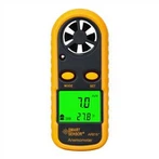
Working principle of wind cup wind speed sensor
The wind cup wind speed sensor is a very common wind speed sensor, which was first invented by Robinson in England. The induction part is composed of three or four conical or hemispherical empty cups. The hollow cup shell is fixed on the three-pointed star-shaped brackets at 120° or on the cross-shaped brackets at 90° with each other. The concave surfaces of the cups are arranged in one direction, and the entire cross-arm frame is fixed on a vertical rotation axis. the
When the wind blows from the left, the wind cup 1 is parallel to the wind direction, and the component force of the pressure of the wind on the wind cup 1 in the direction most perpendicular to the wind cup axis is approximately zero. Wind cups 2 and 3 intersect with the wind direction at an angle of 60 degrees. For wind cup 2, its concave surface faces the wind and bears the largest wind pressure; Smaller than the wind cup 2, due to the pressure difference between the wind cup 2 and the wind cup 3 in the direction perpendicular to the wind cup axis, the wind cup starts to rotate clockwise, the greater the wind speed, the greater the initial pressure difference, and the resulting The greater the acceleration, the faster the wind cup turns.
After the wind cup starts to rotate, because the cup 2 rotates along the direction of the wind, the pressure received by the wind decreases relatively, while the cup 3 rotates at the same speed against the wind, the received wind pressure increases relatively, and the wind pressure difference decreases continuously , after a period of time (when the wind speed remains constant), when the partial pressure difference acting on the three wind cups is zero, the wind cups will rotate at a constant speed. In this way, the wind speed can be determined according to the rotating speed of the wind cup (number of revolutions per second).
When the wind cup rotates, it drives the coaxial multi-tooth disc or magnetic rod to rotate, and the pulse signal proportional to the wind cup speed is obtained through the circuit. The pulse signal is counted by the counter, and the actual wind speed value can be obtained after conversion. At present, the new rotor cup anemometers all use three cups, and the performance of the conical cup is better than that of the hemisphere. When the wind speed increases, the rotor cup can quickly increase the speed to adapt to the airflow speed. However, it cannot drop immediately. The wind speed indicated by the rotary anemometer in the gust of wind is generally too high to become an over-high effect (the average error produced is about 10%)