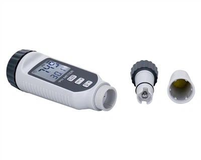
Does a multimeter need to be calibrated when shifting the resistance measurement gear?
The ohm range of a multimeter can be used to measure the resistance of a conductor. The ohm range is indicated by "Ω" and is divided into four ranges: R×1, R×10, R×100, and R×1K. Some multimeters also have an R×10k range. When using the ohm range of a multimeter to measure resistance, in addition to the requirements mentioned before using it, the following steps should also be followed.
1. Set the selector switch to the R×100 range. Short-circuit the two test leads and adjust the ohm zero adjustment knob so that the meter pointer points to the zero position at the right end of the resistance scale line. If the pointer cannot be adjusted to the zero point, it indicates that the battery voltage inside the meter is insufficient, and the battery should be replaced.
2. Touch the two pins of the measured resistor with the two test leads respectively for measurement. Correctly read the resistance value indicated by the pointer, and then multiply it by the multiplier (for the R×100 range, multiply by 100; for the R×1k range, multiply by 1000...). This is the resistance value of the measured resistor.
3. To make the measurement more accurate, the pointer should be made to point near the center position of the scale line during the measurement. If the deflection angle of the pointer is small, switch to the R×1k range. If the deflection angle of the pointer is large, switch to the R×10 range or the R×1 range. After each range change, adjust the ohm zero adjustment knob again, and then perform the measurement.
4. After the measurement is completed, pull out the test leads, set the selector switch to the "OFF" position or the maximum AC voltage range. Put away the multimeter.
The principle of measuring resistance with a multimeter is the single-coil ohmmeter method. Since the resistance values connected in each range of the resistance range are different and increase by a factor of 10, such as ×1, ×10, ×100, ×1000, ×10k. When the terminals are short-circuited, the internal resistance of the battery is in series with the internal resistance of the meter head and the resistance of the ×1 range. When the battery voltage remains unchanged, the current flowing through the coil of the meter head exactly corresponds to the ohm zero position, that is, the terminal voltage of the coil of the meter head corresponding to the zero position is certain. If the resistance values of each range are changed, the terminal voltage of the meter head will change, and the current flowing through the meter head will also change accordingly, and the meter pointer will no longer point to the ohm zero position. For example, when the resistance range is successively changed from the R×1 range to the higher ranges, the voltage of the meter head also decreases successively, the current decreases successively, and the deflection of the pointer will not reach the ohm zero position, which will cause a large measurement error. Therefore, it is necessary to adjust the zero adjustment knob to keep the current of the coil of the meter head unchanged and make the pointer point to the ohm zero position again to ensure the accuracy of each range during measurement.