General Troubleshooting Procedures for Digital Multimeters
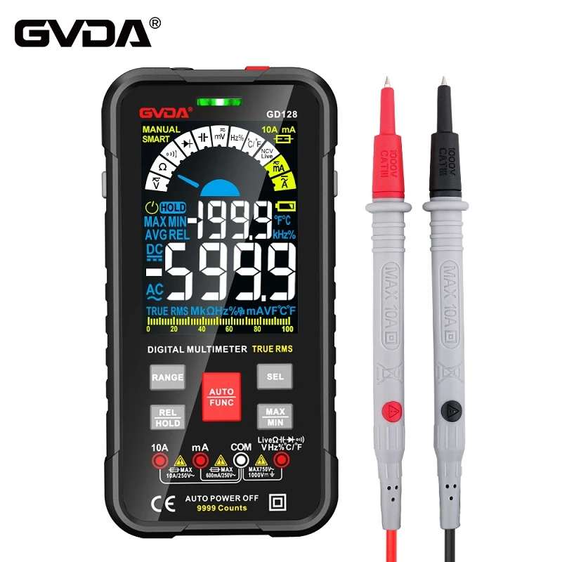
A digital multimeter is a measuring instrument that applies the analog‑to‑digital conversion principle to convert measured quantities into digital values and displays measurement results in digital form. Compared with analog multimeters, it features high accuracy, fast response, high input impedance, digital readout, precise readings, strong anti‑interference performance and a high level of measurement automation, hence it is widely adopted. However, improper operation may easily lead to instrument failures. Taking the DT‑830 digital multimeter as an example, this paper discusses general troubleshooting methods for digital multimeters.
Troubleshooting of digital multimeters generally starts with the power supply. For instance, if there is no LCD display after power‑on, first check whether the 9 V stacked‑battery voltage is too low and whether the battery lead is disconnected. Fault‑searching shall follow the principle of "from outside to inside, from simple to complex". General troubleshooting procedures for digital multimeters are described below.
① Visual Inspection Touch components such as batteries, resistors, transistors and integrated circuits to check for excessive temperature rise. A‑newly‑installed over‑heating battery suggests a potential short‑circuit in the circuit. In addition, inspect the circuit for broken wires, cold‑soldered joints and mechanical damage.
② Measurement of Operating Voltage at Each Stage Measure the operating voltage at each test point and compare readings with nominal
values. Priority shall be given to ensuring the accuracy of the reference voltage. It is recommended to perform measurement and comparison using another identical or similar‑model digital multimeter.
③ Waveform Analysis An oscilloscope is used to observe the voltage waveform, amplitude and period (frequency) at key circuit nodes. For example, verify whether the clock oscillator starts oscillation and whether its oscillation frequency reaches 40 kHz. No output from the oscillator indicates damage to the internal inverter of TSC7106 or an open‑circuit of external components. The waveform at pin 21 of TSC7106 shall be a 50 Hz square wave; otherwise the internal 200‑divider may be defective.
④ Component‑parameter Measurement Perform in‑circuit or out‑of‑circuit measurement and parameter analysis for components within the faulty circuit area. For in‑circuit resistance measurement, account for the influence of parallel components.
⑤ Troubleshooting of Intermittent Faults Intermittent faults refer to failures that occur sporadically, causing the instrument to work intermittently. Such faults are relatively complicated. Common causes include cold‑soldered or loose solder joints, loose connectors, poor contact of rotary switches, unstable component performance and nearly‑broken leads. External environmental factors may also contribute to such faults, such as excessive ambient temperature, high humidity or nearby intermittent strong interference signals.